

Contents
- 1 COsleep: Closed- and Open-loop Sleep Stimulations with Auditory Stimuli
- 1.1 Setup
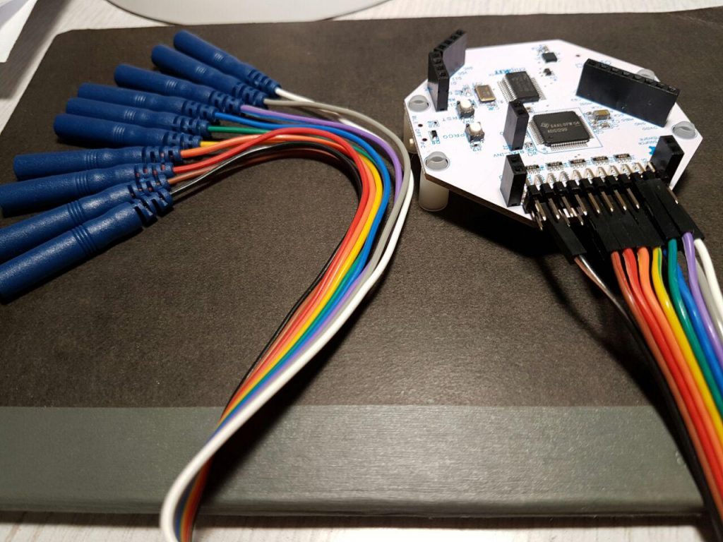
- 1.2 8-channel hardware setup: Main board (no Daisy module)
- 1.3 AASM minimal 8-channel hardware setup AASM minimal setup (and ECG): Main board (no Daisy module)
- 1.4 16 channel hardware setup: Main board + Daisy module.
- 1.5 Run the Software
- 1.6 Trigger/Indicator/Switch
- 1.7 Notes:
- 1.8 Interesting other projects:
COsleep: Closed- and Open-loop Sleep Stimulations with Auditory Stimuli
Following the tutorial on how to get a sleep recording/lab for under $1000 using OpenBCI here a continuation on….
Open Hard- and Software for in-sleep Closed– and Open-loop Targeted and Untargeted Memory Reactivation/Disruption with full-PSG recording.
Stay safe, use hardware and software with caution and on your own risk. The (negative) consequences of auditory stimulation protocols during sleep are sufficiently explored yet.
The github repository with the source (python) and first binary releases.
Only works with OpenBCI Cyton board (from firmware starting at version 2.x.x) and Linux.
So you need a Linux distribution for this to work, I would recommend Ubuntu 18.04 LTS because I tested it, it is used by many, it is easy entry …. and you do not have to be a PC or linux nerd to install it properly and safely. Ubuntu is quick to install, see a tutorial to install Ubuntu alongside Windows … or search the web.
If you are lazy and do not want to install anything, or just try COsleep, install the USB image on an USB stick and boot from it (UEFI and BIOS) with the instructions in this link. A pre-configured Debian Live 9.8.0 distribution with a real-time kernel is on there and ready to run the pre-installed COsleep (executables and source code) from the folder structure found in the root folder /cosleep. Using the USB stick bootable version will (likely) not alter your PC in any way and it works on most common notebooks/laptops/PCs out of the box.
A poster with pictures and infographics, lists’n’stuff shows an example to pack an OpenBCI in a cheap and safe Box. I call it the “Somnofredics Plus PSG”. Its a fun project from a serious collaboration work.
For hardware setup I recommend to read the previous tutorial here.
FYI: The recordings I gained with this setup were comparable to proprietary devices (2 top-of-the-market products from two companies, i.e. parallel recordings on the same electrodes). I am confident in the quality of OpenBCI recordings (the ADS1299 is really worth its high ~$50 price tag over similar cheaper AD-converters). Also confirming Frey (2016) and Rashid et al. (Nov. 2018).
Setup
- EOG (two bipolar electrodes around the eyes)
- EMG (two bipolar electrodes on the chin, musculus mentalis)
- two EEG Deviations at C3 and C4 according to the international 10-20 Electrode placement system (that is C3:A2, C4:A1).
- (optional) further electrodes, mainly in the 16 channel setup and if you have more electrode connectors and electrodes left.
The setup records C3, C3, A1 (left mastoid) and A2 (right mastoid) signals separatly referenced to a placed reference electrode at Cz and uses as a bias Bias/Ground electrode at Fpz (placed at the center of the forehead). one of those electrodes can be replaced to an occipital (e.g. O1 or O2) to be more compliant with AASM. Also there is room for additional channels also in the 8 channel setup.
8-channel hardware setup: Main board (no Daisy module)
| Channel | # Electrodes | Pins to use | Electrode label (cable color) | Type/Function | Location | Comment |
| SRB | 1 | N(bottom) alias SRB2 | Ref (white) | Reference | vertex (~center of head viewed from top) (Cz) | |
| BIAS(2) | 1 | (2 is the bottom pin) | Ground | Ground/Bias | forehead (Fpz) | |
| N1P | 2 | N(bottom), P(top) | EMG1, EMG2 |
EMG | left chin, Right chin |
EMG = EMG2-EMG1 |
| N2P | 2 | N(bottom), P(top) | EOG1, EOG2 |
EOG | 1 cm left of left eye cantus and a little down, 1 cm above right eye center |
EOG = EOG2-EOG1 |
| N3P* | 1 | N(bottom) | A1 | EEG | A1 (bony part behind left ear) | |
| N4P* | 1 | N(bottom) | A2 | EEG | A2 (bony part behind right ear) | |
| N5P* | 1 | N(bottom) | C3 | EEG | C3 (6-8 cm left of vertex towards left ear) | |
| N6P* | 1 | N(bottom) | C4 | EEG | C4 (6-8 cm right of vertex towards right ear) | |
| N7P | [not plugged] | – (unused) | e.g. Fz or bipolar ECG, Trigger signal (red/positive in top P pin) | |||
| N8P | [not plugged] | – (unused) | e.g. Pz or bipolar ECG, feedback channel from stimulation |
AASM minimal 8-channel hardware setup AASM minimal setup (and ECG): Main board (no Daisy module)
| Channel | # Electrodes | Pins to use | Electrode label (cable color) | Type/Function | Location | Comment |
| SRB | 1 | N(bottom) alias SRB2 | Ref (white)/A1 | Reference | A1 (bony part behind left ear) | |
| BIAS(2) | 1 | (2 is the bottom pin) | Ground | Ground/Bias | forehead (Fpz) | |
| N1P | 2 | N(bottom), P(top) | EMG1, EMG2 |
EMG | left chin, Right chin |
EMG = EMG2-EMG1 |
| N2P* | 1 | N(bottom) | EOGL-A1 | EOG | 1 cm left of left eye cantus and a little down, 1 cm above right eye center |
|
| N3P* | 1 | N(bottom) | EOGR-A1 | EOG | 1 cm left of left eye cantus and a little down, 1 cm above right eye center |
|
| N4P* | 1 | N(bottom) | F4-A1 | EEG | F4 (6-8 cm to wards face from vertex, then perpendicular 6-8 cm towards the right, and about 6-8 cm away from C4) | |
| N5P* | 1 | N(bottom) | C4-A1 | EEG | C4 (6-8 cm right of vertex towards right ear) | |
| N6P* | 1 | N(bottom) | O2-A1 | EEG | O2 (12-16 cm to wards back from vertex, then perpendicular 1.5-2 cm towards right side, and 3-4 cm away from O1) | |
| N7P* | 1 | N(bottom) | ECG-A1 | ECG | ECG connected to lower left torso under the heart. | |
| N8P | [not plugged] | – (unused) | Trigger signal (red/positive in top P pin) |
16 channel hardware setup: Main board + Daisy module.
see:
http://openbci.com/forum/index.php?p=/discussion/575/ch-1-8-ok-ch-9-16-railing
http://openbci.com/forum/index.php?p=/discussion/254/soldering-16-channel-openbci-kit
Prior Notes:
- Connect the device’s SRB2 to daisy’s SRB2 and then connect with Reference using a Y cable/bridge (typically provided in the OpenBCI package with the daisy module, but can be build by yourself as well).
- Choose BIAS pin (for Ground electorde) of either daisy module or device, taking one of any of the two is enough, they do not need to be connected.
- Additional 10 electrodes (2×10 connectors) are needed.
- RECOMMEND: You can remove the black and white cable from this connector resulting in 8 additional EEG channels. This avoids confusion them with the Reference (white, connected with a Y cable/bridge) and Ground (black, BIAS) of the first connector the of the setup below.
- RECOMMEND: You can also use these two extra cables for an ECG (e.g. in the free NP8 channel).
| Device | Channel | # Electrodes | Pins to use | Electrode label (cable color) | Type/Function | Location | Comment |
| main | SRB | 1 | N(bottom) alias SRB2 | Ref (white) | Reference | vertex (~center of head viewed from top) (Cz) | connected/linked to daisy module SRB Bottom pin with “Y-bridge” |
| main | BIAS(2) | 1 | (2 is the bottom pin) | Ground | Ground/Bias | forehead (Fpz) | |
| main | N1P | 2 | N(bottom), P(top) | EMG1, EMG2 |
EMG | left chin, Right chin |
EMG = EMG1-EMG2 |
| main | N2P | 2 | N(bottom), P(top) | EOG1, EOG2 |
EOG | 1 cm left of left eye cantus and a little down, 1 cm above right eye center |
EOG = EOG1-EOG2 |
| main | N3P* | 1 | N(bottom) | A1 | EEG | A1 (bony part behind left ear) | |
| main | N4P* | 1 | N(bottom) | A2 | EEG | A2 (bony part behind right ear) | |
| main | N5P* | 1 | N(bottom) | C3 | EEG | C3 (6-8 cm left of vertex towards left ear) | |
| main | N6P* | 1 | N(bottom) | C4 | EEG | C4 (6-8 cm right of vertex towards right ear) | |
| main | N7P | 2 pins | N(bottom),
P(top) |
Negative pole, Positive pole | Trigger | On/OFF Trigger 1000 µV/0µV potential, see below. | |
| main | N8P | 1 | N(bottom) | ECG, reserved, e.g. noise | ECG,Trigger2(EEG) … | another bipolar channel. | |
| daisy | SRB | 1 | N(bottom) alias SRB2 | Ref (white) | Reference | vertex (~center of head viewed from top) (Cz) | connected/linked to main module SRB Bottom pin with “Y-bridge” |
| daisy | N1P* | 1 | N(bottom) | EEG1/F3 | EEG | F3 (6-8 cm to wards nose from vertex, then perpendicular 6-8 cm towards left side, and 6-8 cm away from C3) | |
| daisy | N2P* | 1 | N(bottom) | EEG2/Fz | EEG | Fz (6-8 cm to wards nose from vertex) | |
| daisy | N3P* | 1 | N(bottom) | EEG3/F4 | EEG | F4 (6-8 cm to wards face from vertex, then perpendicular 6-8 cm towards the right, and about 6-8 cm away from C4) | |
| daisy | N4P* | 1 | N(bottom) | EEG4/P3 | EEG | P3 (6-8 cm to wards back from vertex, then perpendicular 6-8 cm towards left side, and 6-8 cm away from C3) | |
| daisy | N5P* | 1 | N(bottom) | EEG5/Pz | EEG | Pz (6-8 cm to wards the back from vertex) | |
| daisy | N6P* | 1 | N(bottom) | EEG6/P4 | EEG | P4 (6-8 cm to wards back from vertex, then perpendicular 6-8 cm towards right side, and 6-8 cm away from C4) | |
| daisy | N7P* | 1 | N(bottom) | EEG7/O1 | EEG | O1 (12-16 cm to wards back from vertex, then perpendicular 1.5-2 cm towards left side, and 3-4 cm away from O2) | |
| daisy | N8P* | 1 | N(bottom) | EEG8/O2 | EEG | O2 (12-16 cm to wards back from vertex, then perpendicular 1.5-2 cm towards right side, and 3-4 cm away from O1) |
(*) Output of these channels have inverted polarity since referenced to the SRB2 pin
Overview of the setup and suggested electrode positions on the head

Run the Software
Great you have your hardware setup and want to run and configure COsleep software to run.
I would recommend to run it from an USB stick or the compiled version of Ubuntu 18.04 LTS.
To quickest way to start is from the cosleep main folder (on the USB stick version this is under /cosleep)
You need to go into the folder cosleep/software/rec_stim and run the executable recording_stimulator.
Assuming you do not want to run an stimulation experiment and just record or get the OpenBCI (with the standard 8 or 16 channel setup from above), that is all you need to do.
The dialogs depend on each other and if you choose certain options, others become available.
Now you can just click through the dialogs and read them, try to make sense of them or play around changing the standard settings:
- At the beginning you need to give a subject number
- Then if you like the default settings (or have more detailed dialogs). Let’s choose the default settings.
- Then the number of channels (if you do not have a daisy module attached, 8 is what you should choose).
- Then if we want the Full signal viewer, that is if we want to see the signal of all 8/16 channels in addition to the standard one, I would recommend to choose the option “Only Recording View” with only the EEG, EOG and EMG channel signals displayed, because who needs to look an more? You do?! well then pick the option “Full Signal Viewer”.
- If you picked 8 channels before, then pick your sampling rate for the display and connection (this is NOT for the SD card, SD card is always 250 Hz). If you have only 8 channels, you can sample at 250 Hz or 125 Hz, if you want to record 16 channels, you do not have this option, it will be 125 Hz maximum, but who needs more anyway.
- Now you can choose to record on an SD card, default is not to (because from my experience this can make the recording more unstable and often stop the connection after one hour in some devices). If you want to record on SD card, there are more optoins on how long you want to record. Note that recording with 16 channels makes the maximum SD card recording times different from having chosen to record in 8 channels. Then anohter dialog pops up if you want to record in SD card where you choose to see the recording also in real-time in the Signal Viewer or if you just want to record on SD card and leave it at that. If you choose to only record on SD card, and do not need a viewer, then jump to point number 10. with the last dialog.
- … or maybe some dialogs later, choose if you only want to record or do an auditory stimulation. Lets just record for now.
- Then you select the language for the instructions given to the subjects, for now Chinese and English are in there. The interface itself is still in English no matter what you chose here.
- Then you have to select if you actually want to record from a real OpenBCI Device. If you want to use a previous recording and simulate a recording, then choose “Simulation (CSV)” (not to confuse with Stimulation). But now lets record from a real device.
- The last dialog is then the one for the connection to the device, READ IT, if you are confident you did everything right until now, press OK, after some while e.g. 30 seconds up to two minutes you will either find a warning, the same dialog, another message or the Viewer with the live data progressing to pop up… if the latter is the case then congrats, you are recording data now and find the results in the folder cosleep/software/rec_stim/data/rec with resulting files matching the entered subject number of Dialog 1 and the date of recording. Happy hacking.
A more detailed tutorial on the software will maybe follow later.
Trigger/Indicator/Switch

Notes:
- Sound buffer. If you do a Stimulation protocol, make sure to not choose a too short sound buffer. The default is 1024 audio samples at 44.1 kHz corresponding to about 23 ms. The safest option is 4096 audio samples at 44.1 kHz corresponding to about 93 ms delay of the sound. This delay is considered by the stimulation algorithsm for the playing of the sounds. For example, at the safe 4096 setting, if a delay of 0.2 s after threshold determination is chosen for closed-loop stimulation, this 0.2 seconds corresponds to 0.107 s + 0.93 s = 0.2 s, where at 0.107 s the conditions for playing the sound are checked The accuracy of timing is the duration of a sample of the signal. The sound buffer can typically reduced to 1024 audio samples (about 23 ms delay), but at lower than this distortions of the sound or cracking noise can be the result. In the log files of the terminal output there are typically “alsa … underrun occured …” messages, that indicate hard- or software could not keep up with accurate presentation of stimuli (typically the software is stuck to present the full samples for the alsa audio pipeline). With (very) good dedicated hardware 256 a delay samples are realistic, but please check if it works, and you do not hear any cracks in the sound. If accuracy of sound is not your issue, but delay is, choose lower delays.
- Filtering for the stimulation algorithm (equivalent as the signals viewed in the GUI). The filter is by default a high-pass filter of 0.16 Hz and a low-pass filter of 30.0 Hz for EEG and EOG, and a high-pass filter of 10 Hz for EMG. The filter is a one-pass Butterworth filter that can distort the signals and shift samples by on average half of a sample length multiplied by the filter order it. The shift is depending on the frequency component of the signal. The signal delay is mainly dependent on the low-frequency high-pass filter:
- At 125 Hz the filter order is 1 sample. Thus signal is approximately delayed by 0.5 samples (= 0.5*8 ms = 4 ms)
- At 250 Hz the filter order is increased to 2 samples. Thus signal is approximately delayed by 1 sample (= 4 ms)
- Performance improvements to run the frontend GUI and the backend algorithm. The backend algorithm typicall runs very smooth an a modern PC/laptop/notebook with no need for limitations. The frontend can be more of a slow thing and depends on your hardware much more. Here are some things you can do to improve performance:
- Choose better PC hardware: more CPU power is better, for GUI processing also a good GPU that is supported by your linux distribution or has a good driver installed can speed up things. Also a good hard drive like a modern SSD goes a long way and avoids bottlenecks for writing the data on the hard drive
- Configure the startup of COsleep, make sure you choose “Details” instead of “Default”option:
- Choose the non-default “No anti-aliasing” option in the opening dialog, that makes the signal in the GUI look worse but sufficient. This mainly makes the GUI frontend faster, but can save some CPU power for the backend as well.
- Choose the non-default “OpenGL”in the opening dialog for view processing in the GUI, that makes use of your hardware better. This mainly makes the GUI frontend faster, but can save some CPU power for the backend as well.
- When using a 8 channel recording then use the non-default “125 Hz (odd)” instead of the default “250 Hz (all)”, that uses only 125 Hz even though the 250 are available. On the SD card there is always 250 Hz sampling rate stored. 125 Hz is typically enough for standard EEG, EOG and ECG (and sufficient for the vast majority of sleep analyses and beyond), also EMG signals are is typically good enough displayed. You need a lot of good ERP signals grouped together to really start talking about more than 40 Hz signals and their shape. This makes the GUI frontend and the backend faster.
- Do not use the Extended Signal view for a second window of signals and choose “Only Recording View (fast refresh rate)” but if you must you can make a Montage with only the most necessary channels to view there extra to the Main signal view window, just place a “no” without the quotes in the montage .tsv file in the column called GUI_signalviewer_order. This makes the Main GUI frontend faster, and the backend a little bit too.
- Disable the default “Highlight spindles” optioin to “OFF”, who needs aid in finding spindles anyway. This makes the GUI frontend faster.
- Do not write in EDF or BDF. Though this saves very little backend performance, it can be critical on slow hard drives, especially in longer recordings.
- Consider what you really need for your purpose, are 8 channels with 125 Hz recording enough, and you do not need so much functionality to improve your outcomes in a relevant way…then go for that simple way.
- (on a standard 2012 subnotebook with i5 dual processor, Lenovo Thinkpad X220, stable refresh rates of 0.3 s and below could easily be achieved in any setting or startup option.)
Interesting other projects:
OpenNFB: https://strfry.org/blog/opennfb.html https://strfry.org/blog/openbci-review.html, https://github.com/strfry/OpenNFB
Traumschreiber: https://www.traumschreiber.uni-osnabrueck.de/ https://github.com/mvidaldp/Traumschreiber-mobileEEG https://github.com/StatefulMind/eegdroid https://github.com/pnieters/tflow_edge https://github.com/adrocampos/EEG-Droid