

Contents
A sleep lab for less than $1000 with OpenBCI
DISCLAIMER: Use these instructions on your own risk. It is critical to understand that the devices and methods presented here are in no means a safe and tested setup and they do not adhere to medical standards!
Keep all devices only running on batteries and NEVER attach them to living things like humans without making 100% sure they are disconnected (COMPLETELY) from the power grid/plug/line etc.!
Also make sure that no bare wires or electordes can get in contact with the head-attached device or electrodes and make sure the power connectors (from battery) are fixed and do not get in connectact with the electrodes or contacts to the head.
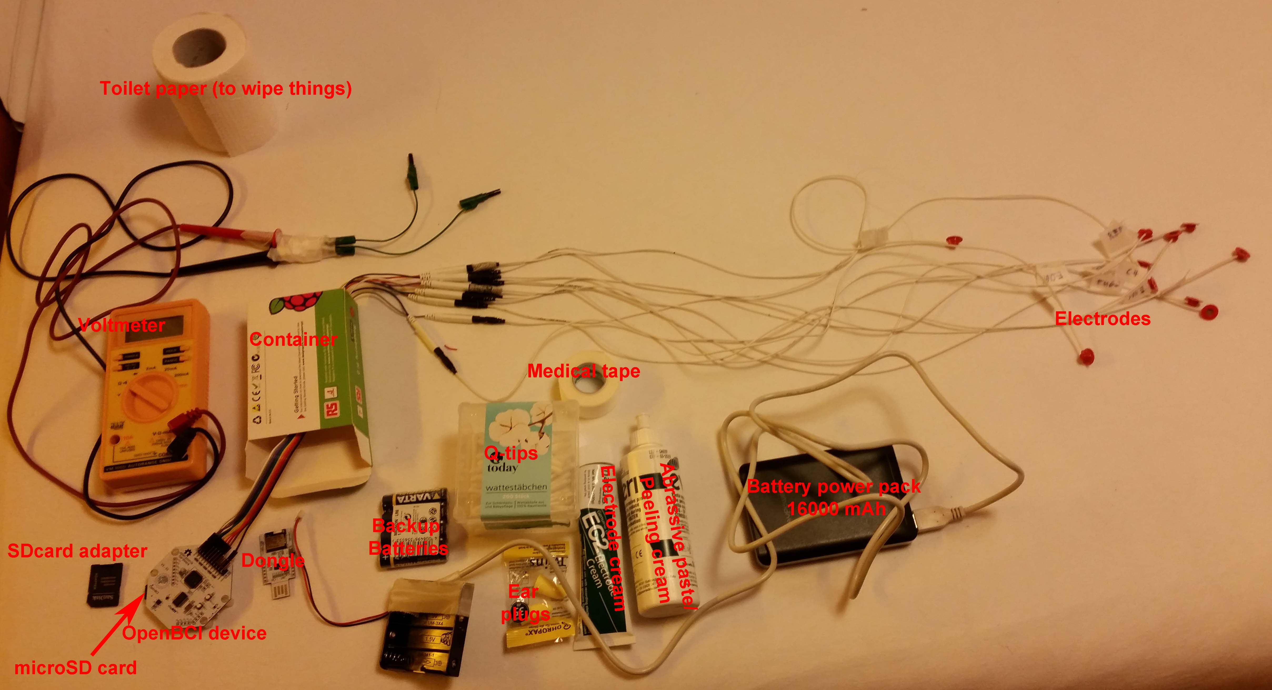
On multiple request I want to introduce OpenBCI as a cheap alternative to record standard polysomnography. With this and SpiSOP you could in principle built your own private sleep research lab now for under $1000 now, everyting included:
- mobile EEG and all neccessary materials $650-700
- PC and monitor $100 (rasperry pi 3, and old Monitor from ebay etc.)
- Bed and sheets etc. $199
- Software $0 (e.g. using SpiSOP)
- Room, there is always “free” room somewhere you can sleep, especially overnight.
I recommend the OpenBCI Cyton (previously known as 32bit Board Kit) as a mobile EEG for polysomnography:
Cyton Biosensing Board (8-channels)
or
Cyton Biosensing Board + Daisy Module (16-channels)
or alternatively from:
http://pirate.info/producten/open-source-hardware/openBCI (also for self assembly, it is about $250 if you assemble the 16-channel version (with daisy module) yourself with all parts included, most expensive part is the ADS1299 chip each around $50-60).
Similar (newer) Projects not OpenBCI:
- OpenLD including similar to OpenBCI but developing an own open-source and open-hardware platform just dedicated to sleep, in particular REM sleep (and lucid dreaming) https://hackaday.io/project/13285-openld-lucid-dreaming-research-platform
- FreeEEG32 has 8 channels for every “e” in its name (=32), instead of the ADS1299 chip of the OpenBCI (or two including the daisy module) for analog to digital converters (from Texas Instruments), this board uses four AD7770 chips (from Analog Devices). https://hackaday.io/project/20618-freeeeg32-32-channels-electroencephalography
Here my highlights in brief for the OpenBCI Cyton EEG device:
- + cheap: ~$500 each (the newer 4 channel “Ganglion” devices are $100, however not usable for complete standard polysomnography), invest a little more and you get electrodes with it and stuff, or assemble yourself if you have the time and know how to deal with PCB plates (it is open hardware after all)
- + 8 channel recording (extendable to 16 channel, using an extra module (daisy module), 8 is fine though)
- + all channels can be bipolar (e.g. for EMG, and EOG, then two electordes give one channel)
- + sample rate is 250 Hz (seems it can vary depending +-0.4 Hz, I guess depending on room temperature, not enough to impair precision of sleep scoring, a sample rate of 250.4 Hz seems more accurate for a tested device at ~21°C)
- + recording is with 24 bit signal precision. In reality the signal resolution is up to 0.02235 microVolts at 24x gain (default, see Table 1 below). They are stored as 6 hex values (= 24 bit) on the SD card and. Usually 0.1 microVolts is more than enough for EEG and ECG and EMG etc. and noise is anyway about (0.16 microVolts root-mean-squared, recording the same channel deviation C3:A2 directly or rereferenced gave a noise of about +-0.6µV, that is awesome!). The signal range is more than sufficient at any gain value.
- + can be initialized (and sampled) over the air (via bluetooth)
- + runs on battery and is mobile (e.g. with a little soldering runs on on a power pack like this for days without recharge! http://www.ravpower.
de/16750mah-portable-charger- black.html but caution with the voltage range of the different borad types, I uses the 32bit Cyton version). Input to the OpenBCI 32bit Board/Cyton is 3V to 6V (so very flexible indeed, runs on 5V USB and 3.7 V LiPo batteries, or 3 to 4 of 1.5 V Mignon Battery coupled in series) - + recordings are on micro SD card (needs to be bought separately)
- – no trigger out of the box (so no lights-off moment) – however will be possible with newer Firmware soon, and you can use a channel to take a kind of trigger signal (no problem with rasperry pi hardware et al. running on batteries, or your laptop running on batteries and not being pluged in for charging). However see simple Trigger builtbelow.
- – no easy and reliable live monitoring of the recording (sometimes interrupted if not carfully handled, bluetooth connection is not that reliable)
- – does not run out of the box, and no sleep scoring software (there is however plenty of freeware on that… and you can use SpiSOP for that of course)
- – data format needs to be converted to brainvision or EDF format, but conversion is in fact very easy (https://www.spisop.org/
downloads/ see conversion utilities) - – needs to be packed in a box for protection of the circuits (if you want to be on the safe side)
Table 1: Signal resolution and range
| Signal resolution [microVolts] | Gain [amplifier] | Signal range [microVolts] |
| 0.02235 | 24 | -187500 to 187500 |
| 0.04470 | 12 | -375000 to 375000 |
| 0.06706 | 8 | -562500 to 562500 |
| 0.08941 | 6 | -750000 to 750000 |
| 0.13411 | 4 | -1125000 to 1125000 |
| 0.26822 | 2 | -2250000 to 2250000 |
| 0.53644 | 1 | -4500000 to 4500000 |
Hardware Setup
| Channel | # Electrodes | Pins to use | Electrode label (cable color) | Type/Function | Location | Comment |
| SRB | 1 | N(bottom) alias SRB2 | Ref (white) | Reference | vertex (~center of head viewed from top) (Cz) | |
| BIAS(2) | 1 | (2 is the bottom pin) | Ground | Ground/Bias | forehead (Fpz) | |
| N1P | 2 | N(bottom), P(top) | EMG1, EMG2 |
EMG | left chin, Right chin |
EMG = EMG1-EMG2 |
| N2P | 2 | N(bottom), P(top) | EOG1, EOG2 |
EOG | 1 cm left of left eye cantus and a little down, 1 cm above right eye center |
EOG = EOG1-EOG2 |
| N3P* | 1 | N(bottom) | A1 | EEG | A1 (bony part behind left ear) | |
| N4P* | 1 | N(bottom) | A2 | EEG | A2 (bony part behind right ear) | |
| N5P* | 1 | N(bottom) | C3 | EEG | C3 (6-8 cm left of vertex towards left ear) | |
| N6P* | 1 | N(bottom) | C4 | EEG | C4 (6-8 cm right of vertex towards right ear) | |
| N7P | [not plugged] | – (unused) | e.g. Fz or bipolar ECG, trigger signal (red/positive in top P pin) | |||
| N8P | [not plugged] | – (unused) | e.g. Pz or bipolar ECG, feedback channel from stimulation |

| Channel | # Electrodes | Pins to use | Cable color | Label (electrode) | Type/Function | Location | Comment | |
| SRB | 2 | N(bottom) alias SRB2 | white | Ref (A1-A2) | Reference (linked) | (linked A1 and A2 with an electrode bridge) | ||
| BIAS | 1 | 2 or N (bottom) | black | Ground | Ground/Bias | forehead (Fpz) | ||
| N1P | 2 | N(bottom), P(top) | grey, purple | EMG1, EMG2 |
EMG | left chin, Right chin (musculus mentalis) |
EMG = EMG1-EMG2 |
|
| N2P | 2 | N(bottom), P(top) | blue, green | EOG1, EOG2 |
EOG | 1 cm left of left eye cantus, 1cm above right eye center |
EOG = EOG1-EOG2 |
|
| N3P | 2 | N(bottom), P(top) | yellow,orange | A2, C3 (C3:A2) | EEG | A2 (bony part behind right ear), C3 (6-8 cm left of vertex towards left ear) |
||
| N4P | 2 | N(bottom), P(top) | red, brown | A1, C4 (C4:A1) | EEG | A1 (bony part behind left ear), C4 (6-8 cm left of vertex towards right ear) |
||
| N5P | [not plugged] | – (unused) | – (unused) | e.g. Fz:A1-A2 or bipolar ECG | ||||
| N6P | [not plugged] | – (unused) | – (unused) | e.g. Pz:A1-A2 or bipolar ECG | ||||
| N7P | [not plugged] | – (unused) | – (unused) | e.g. Cz:A1-A2 or bipolar ECG | ||||
| N8P | [not plugged] | – (unused) | – (unused) | e.g. Oz:A1-A2 or bipolar ECG |
Software Setup
USE COsleep, see here and save your time in installing and setting up the OpenBCI_GUI, all you need is a running Ubuntu 18.04 LTS which can be installed in parallel on most systems in a few minutes, or even can be run from an USB stick directly without the need to alter anything on your PC.
- Prepare connections and setup electrodes and OpenBCI device (see section above on Hardware setup for this).
- Better check if the latency on your PC is fixed to 1 ms or so, e.g. for Windows this is necessary to do once, see here how to do this http://docs.openbci.com/tutorials/10-OpenBCI_on_Windows)
- Prepare the microSD card for new recording, this means delete/backup/save previous files on there (if not formated in FAT32 then http://docs.openbci.com/tutorials/10-OpenBCI_on_Windowsdo so now, see SD card basics for how to do so, it is important that the SD card is formated correctly, otherwise the data will not write properly (e.g. SDFormater 4.0 Option: “FULL(OverWrite) FORMAT, FORMAT ADJUSTMENT OFF”), SD cards of “Class 4” seems to be sufficient although “Class 10” is recommended), it does not seem to matter if other (non-OpenBCI) files are on the card once it was formatted, an microSD to SD adapter for your PC and a SD card reader is required of course for this).
- Check if the dongle switch is turned on “GPIO_6” NOT “RESET”.
- Put in the microSD card in the OpenBCI device.
- If something goes wrong from here on now, start from this step again
- Plug in dongle first (until blue light is on), if it is plugged in plug it out and then in again.
- Turn on OpenBCI device, that is put the switch on “PC” NOT “BLE” (ideally you should see one or two very short red blinks on the OpenBCI dongle after the OpenBCI device was turned on, this is a good sign, but does not have to occur), if you have a trigger cable also check if it is connected and plugged to the power.
- Start the OpenBCI_HUB and then the OpenBCI_GUI (prefereably in the Processing version or a new exported version of it, get it here https://github.com/OpenBCI/OpenBCI_Processing or use one of the newer compiled versions http://openbci.com/index.php/downloads e.g. version 3.3.1, Windows and Mac version work nicely).
- Start a “Live Session” or “Live (from Cyton)” for 8 channels (16 if you have the Daisychain module), with SD card recording length of e.g. 12 hours, 8 channels (giving a file name is irrelevant since you record on the SD card)
- Edit all your channels (click “Hardware settings” in the top left for this) for the recording to follow (all with gain of 24, this also works fine for the sleep EMG), see the Tables below for the setup.
- Press “Start Data Stream” (this is the start when data gets written to the SD card)
- Wait 2 seconds
- Pull out the dongle form the USB port on the PC (yes, just pull it, SD recording will continue for the 12 hours you set up, OpenBCI software will loose connection of course)
- Wait until you have recorded your sleep etc. to be written on a your file (e.g. “OBCI_0C.TXT”) to be written to the SD card.
- When finished, just turn the OpenBCI device off,
- The SD file was saved on the SD card and you can copy and convert on your PC (see below)
Channel setup in OpenBCI_GUI for the preferred setup (things to change from default in bold):
| Channel | Status | Label | Gain | InputType | Bias | SRB2 | SRB1 | Init. Sequence |
| 1 | ON | EMG | x24 | Normal | Don’t include | OFF | NO | x1060000X |
| 2 | ON | EOG | x24 | Normal | Don’t include | OFF | NO | x2060000X |
| 3 | ON | A1 | x24 | Normal | Include | ON | NO | x3060110X |
| 4 | ON | A2 | x24 | Normal | Include | ON | NO | x4060110X |
| 5 | ON | C3 | x24 | Normal | Include | ON | NO | x5060110X |
| 6 | ON | C4 | x24 | Normal | Include | ON | NO | x6060110X |
| 7 | OFF(if unused)/ ON (if Trigger cable used) | – | x24 | Normal | Don’t include | OFF | NO | x7160000X / x7060000X |
| 8 | OFF(unused) | – | x24 | Normal | Don’t include | OFF | NO | x8160000X |
For details see (http://docs.openbci.com/OpenBCI%20Software/01-OpenBCI_SDK)
x1060000Xx2060000Xx3060110Xx4060110Xx5060110Xx6060110Xx7160000Xx8160000XK
Conversion of (micro-)SD card File
…to EEG file formats like EDF or Brainvision
There is a conversion script (https://www.spisop.org/
| Channel Label | Filter | Usage |
| EOG | 0.3-35 Hz | scoring eye movements/blinks |
| C3:A2 | 0.3-35 Hz | scoring EEG |
| Cz:A1A2 | 0.3-35 Hz | additional EEG deviation |
| C4:A1 | 0.3-35 Hz | scoring EEG backup channel |
| C3:Cz | 0.3-35 Hz | original EEG deviation |
| C4:Cz | 0.3-35 Hz | original EEG deviation |
| A1:Cz | 0.3-35 Hz | original EEG deviation |
| A2:Cz | 0.3-35 Hz | original EEG deviation |
| EMG | 10-125 Hz | scoring muscle and artifacts |
| C3:A2fspind | 11.5-15 Hz | aid in fast spindles |
| C3:A2sspind | 8.5-11.5 Hz | aid in slow spindles/alpha |
| C3:A2SO | 0.5-2 Hz | aid in slow oscillations/waves/K-complexes |
| C3:A2theta | 4-8 Hz | aid in theta |
| C3:A2alpha | 8-12 Hz | aid in alpha detection |
For this extract the utility.zip (downloaded from https://www.spisop.org/downloads/ under see conversion utilites) to your SpiSOP folder (e.g. “D:\spisop_toolbox_beta2.3” resulting in a “D:\spisop_toolbox_beta2.3\utility\convert_data” folder\…); if you did not have installed SpiSOP yet, just do it now (it is just extracting it to some location like “D:\spisop_toolbox_beta2.3” by skipping steps 3 and 6 from this Instruction)
Then put the “OBCI_??.TXT” File(s) from your recording in the conversion folder (e.g. D:\spisop_toolbox_beta2.3\utility\convert_data\OpenBCIv3\convert_SD_file\SD_to_ascii_then_to_EEG)
Then edit the “obci_convert_gain24_constant_trigger.bat” in that folder for the SpiSOP toolbox folder and give correct paths to the toolbox, and run it, wait a little and you have your converted files!
e.g. change
...
SET pathPrefix=D:\spisop_toolbox_beta2.3
...
to fit your SpiSOP folder path.
You can use these converted files to do sleep scoring with the SpiSOP browser function, and do other cool stuff with your sleep EEG with other SpiSOP functions.
Now you can feel like a sleep resercher and detect your own sleep!
16 channel setup: Main board + Daisy module.
see:
http://openbci.com/forum/index.php?p=/discussion/575/ch-1-8-ok-ch-9-16-railing
http://openbci.com/forum/index.php?p=/discussion/254/soldering-16-channel-openbci-kit
Prior important Notes:
- No need to connect the BIAS of device and daisy module (taking one of any of the two is enough)
- Connect the device’s SRB2 to daisy’s SRB2 and then connect with Reference using a Y cable/bridge (typically provided in the OpenBCI package with the daisy module, but can be build by yourself as well).
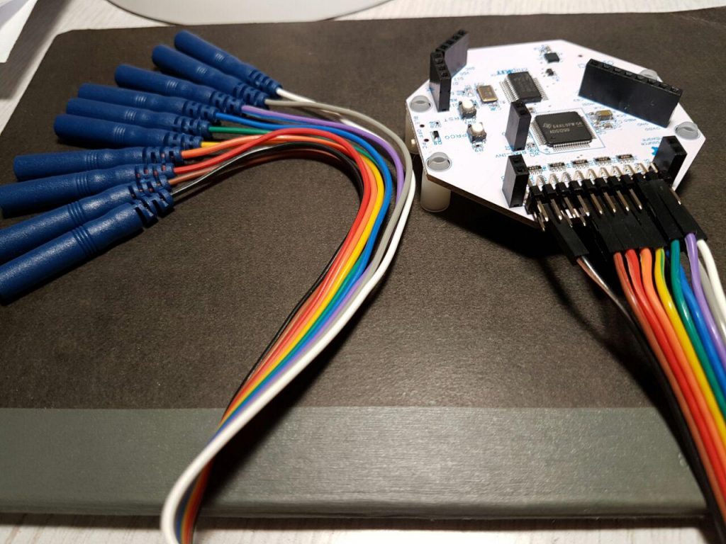
- You need a second connector cable with 10 additional electrodes. For example you can remove the black and white cable from this connector resulting in 8 additional EEG channels, … removing them avoids confusion them with the Reference (white, connected with a Y cable/bridge) and Ground (black) of the first connector the of the setup below. But you can also use these two extra cables for an ECG.
| Device | Channel | # Electrodes | Pins to use | Electrode label (cable color) | Type/Function | Location | Comment |
| main | SRB | 1 | N(bottom) alias SRB2 | Ref (white) | Reference | vertex (~center of head viewed from top) (Cz) | connected/linked to daisy module SRB Bottom pin with “Y-bridge” |
| main | BIAS(2) | 1 | (2 is the bottom pin) | Ground | Ground/Bias | forehead (Fpz) | |
| main | N1P | 2 | N(bottom), P(top) | EMG1, EMG2 |
EMG | left chin, Right chin |
EMG = EMG1-EMG2 |
| main | N2P | 2 | N(bottom), P(top) | EOG1, EOG2 |
EOG | 1 cm left of left eye cantus and a little down, 1 cm above right eye center |
EOG = EOG1-EOG2 |
| main | N3P* | 1 | N(bottom) | A1 | EEG | A1 (bony part behind left ear) | |
| main | N4P* | 1 | N(bottom) | A2 | EEG | A2 (bony part behind right ear) | |
| main | N5P* | 1 | N(bottom) | C3 | EEG | C3 (6-8 cm left of vertex towards left ear) | |
| main | N6P* | 1 | N(bottom) | C4 | EEG | C4 (6-8 cm right of vertex towards right ear) | |
| main | N7P | 2 pins | N(bottom),
P(top) |
Negative pole, Positive pole | Trigger | On/OFF Trigger 1000 µV/0µV potential, see below. | |
| main | N8P* | 1 | N(bottom) | reserved, e.g. noise | EEG, ECG,Trigger2 … | ||
| daisy | SRB | 1 | N(bottom) alias SRB2 | Ref (white) | Reference | vertex (~center of head viewed from top) (Cz) | connected/linked to main module SRB Bottom pin with “Y-bridge” |
| daisy | N1P* | 1 | N(bottom) | EEG1/F3 | EEG | F3 (6-8 cm to wards nose from vertex, then perpendicular 6-8 cm towards left side, and 6-8 cm away from C3) | |
| daisy | N2P* | 1 | N(bottom) | EEG2/Fz | EEG | Fz (6-8 cm to wards nose from vertex) | |
| daisy | N3P* | 1 | N(bottom) | EEG3/F4 | EEG | F4 (6-8 cm to wards face from vertex, then perpendicular 6-8 cm towards the right, and about 6-8 cm away from C4) | |
| daisy | N4P* | 1 | N(bottom) | EEG4/P3 | EEG | P3 (6-8 cm to wards back from vertex, then perpendicular 6-8 cm towards left side, and 6-8 cm away from C3) | |
| daisy | N5P* | 1 | N(bottom) | EEG5/Pz | EEG | Pz (6-8 cm to wards the back from vertex) | |
| daisy | N6P* | 1 | N(bottom) | EEG6/P4 | EEG | P4 (6-8 cm to wards back from vertex, then perpendicular 6-8 cm towards right side, and 6-8 cm away from C4) | |
| daisy | N7P* | 1 | N(bottom) | EEG7/O1 | EEG | O1 (12-16 cm to wards back from vertex, then perpendicular 1.5-2 cm towards left side, and 3-4 cm away from O2) | |
| daisy | N8P* | 1 | N(bottom) | EEG8/O2 | EEG | O2 (12-16 cm to wards back from vertex, then perpendicular 1.5-2 cm towards right side, and 3-4 cm away from O1) |
Here a short overview of the setup and where the electrodes suggested above are placed

Channel setup in OpenBCI_GUI for the preferred setup (things to change from default in bold):
| Channel | Status | Label | Gain | InputType | Bias | SRB2 | SRB1 | Init. Sequence |
| 1 | ON | EMG | x24 | Normal | Don’t include | OFF | NO | x1060000X |
| 2 | ON | EOG | x24 | Normal | Don’t include | OFF | NO | x2060000X |
| 3 | ON | A1 | x24 | Normal | Include | ON | NO | x3060110X |
| 4 | ON | A2 | x24 | Normal | Include | ON | NO | x4060110X |
| 5 | ON | C3 | x24 | Normal | Include | ON | NO | x5060110X |
| 6 | ON | C4 | x24 | Normal | Include | ON | NO | x6060110X |
| 7 | ON | Trigger | x24 | Normal | Don’t include | OFF | NO | x7060000X |
| 8 | ON | reserved | x24 | Normal | Don’t include | OFF | NO | x8060000X |
| 9 | ON | EEG1/F3 | x24 | Normal | Include | ON | NO | xQ060110X |
| 10 | ON | EEG2/Fz | x24 | Normal | Include | ON | NO | xW060110X |
| 11 | ON | EEG3/F4 | x24 | Normal | Include | ON | NO | xE060110X |
| 12 | ON | EEG4/P3 | x24 | Normal | Include | ON | NO | xR060110X |
| 13 | ON | EEG5/Pz | x24 | Normal | Include | ON | NO | xT060110X |
| 14 | ON | EEG6/P4 | x24 | Normal | Include | ON | NO | xY060110X |
| 15 | ON | EEG7/O1 | x24 | Normal | Include | ON | NO | xU060110X |
| 16 | ON | EEG8/O2 | x24 | Normal | Include | ON | NO | xI060110X |
For details also see (http://docs.openbci.com/OpenBCI%20Software/01-OpenBCI_SDK)
For the nerds: Initialization sequence to sent to OpenBCI device for a 12 hour recording on the microSD card and 16 channels (by OpenBCI software, or by OpenVIBE http://openvibe.inria.fr/):
Cx1060000Xx2060000Xx3060110Xx4060110Xx5060110Xx6060110Xx7160000Xx8060000XxQ060110XxW060110XxE060110XxR060110XxT060110XxY060110XxI060110XK
Conversion of the 16 channels (and also backwards compatible with 8 channels): replace the SD_to_ascii_then_to_EEG with the SD_to_ascii_then_to_EEG_16_channel found in this zip and look at the examples given there.
Considerations
Power consumption and how long does it last?:
The power consumption of the 32bit/Cyton 8 channel device is (as measured by my standard Voltmeter) about ~50 mA in idle mode, ~65 mA in connected mode, and ~75 mA while streaming and recording on SD card. So a 16000 mA 5 V USB power pack can last fully charged (in principle) for up to 8 days through.
To prevent (yourself and) others to charge the power pack while connected with your OpenBCI: TAPE THE PLUG AS TO NOT MAKE YOUR POWER PACK CHARGEABLE WHILE USING IT AS A POWER SOURCE FOR A DEVICE CONNECTED TO YOUR HEAD!
Many power packs however shut down after a few seconds if the current is below a certain threshold (the ealier version of the Ravpower with 14000 mAh, Model RP-PB13, requires >95 mA current draw). The above mentioned Ravpower pack with 16000 mAh with iSmart output maybe does not have this limitation. This threshold is obviously to high since the OpenBCI device needs less than 95 mA. So if it is just connected the Power pack cuts the power after a few seconds again. However this can be solved:
Solution 1 (Quick): Turn on the LED flashlight while powering the OpenBCI device (and cover the flashlight with some opaque tape to make it not shine all night). This draws a lot of power though.
Solution2 (better): bridge the power source with a 100 Ohm resistor. USE A RESISTOR THAT CAN WITHSTAND 1 W OF POWER (most resistors are not built for this I would recommend using metal film resistors, NOT carbon film resistors), otherwise the resistor (and things near it) will get very hot (or burned)! This resistor will pull ~50 mA from the 5 V battery pack when turned on. This is enough to keep your device running (ONLY) if your OpenBCI device is powered. If the device is not turned on, then (magically) the power pack shuts down automatically after a few seconds. The resulting power consumption is 72 mA + 50 mA = 122 mA (still not much as you can power your device about 5 days straight with one charge of the recommended power pack).
Solution3 (best): get a power pack that does not power down on low power draws. e.g. https://www.ravpower.de/12000mah-portable-charger-black.html or the 22000 mAh version, Model RP-PB052, from https://www.ravpower.com/portable-charger.html which I tested to not shut down on low power draw and idle OpenBCI device, it thus will theoretically last to power the device for 12 days!
True sample rate and variation in time data:
A short test on an 8-hour recording at usual Central European room temperatures (22° C) lead to the conclusion that the sample rate was overall (on average) faster than the 250 Hz (that is about 250.4 Hz) leading to approximately a 1 minute extra of displayed recording time in an 8 h of recording when it was in fact shorter. In conclusion the sampling rate varies over the recording, It is unclear how much it varies within this time frame and how stable the sampling rate is over longer terms (that is, is it 250.4 Hz all the time or not? This needs still to be determined). It is also unclear how this changes from device to device. This altering sampling rate makes sense when one consideres that there was no external oscillator (clock) used on the board.
high density EEG? Well yes why not, should work in principle (with limitations)!:
You can record with several devices at the same time. Each device than has to share the same bias and reference electrodes via a bridged, and also share one additional channel (e.g. EEG) via a bridge. Later the signals from the many devices can be concatenated using signal coherence of the shared EEG channel (via cross-correlation with the lag of the peak in correlation value as an adjustment). Feasible are at least 4 devices each with 16 channels, that is including EMG, ECG and EOG (3 channels) in one device and one shared channel for the others = (16-3) + (16-1) + (16-1) + (16-1) = 58 EEG at 125 Hz (and potentially more when the Wifi shield is out)…. for a device around $4000. You just start recording of those devices one after the other on SD card… later concatenate the signals after the recording is finished. This makes it unfeasible now to monitor all channels live on the same PC (however could be achieved by running several instaces of the OpenBCI GUI, and plugging in all the dongles at the same time). Imporantly, if you merge the data later you need to consider that the sampling rates of each device was not synched! This leads to time uncertainty in each channel and limits the use of the concatenated data, that is you cannot use it for timelocked analysis accross channels of different devices (e.g. slow waves in channel 1 recorded with device 1 timelocked to spindles in channel 11 recorded with device 2. However it should be fine for counting spindles or spindle density/slow wave density, or do channel-wise analyses.
A casing for OpenBCI and Security:
Any (non-metal inside) box will do that can hold battery and device at the same time and maybe can be carried around. You can shield it further with Aluminum around the case. And nothing keeps you from stuffing it in a nice teddy bear to go to sleep or send others to sleep with. It is however highly recommended to isolate the device first in some thicker plastic before rapping it in something conductive (e.g. non-conductive tape) and keeping it away from sharp things that could demage the contacts or the board circuits (e.g. a dry kitchen sponge)!
You can also consider to Plastidip it or put some hot glue around any open contacts and wires that might get short circuited.
Troubleshooting
- Connection of dongle and device cannot be established and the dongle LED is blinking red shortly a few time but then breaks off. If in this case it works (after shutting down the device, reconnect the dongle, turn on device again) to connect WITHOUT SD card (and initialization of it) then your SD card is probably formatted wrong or full or not compbatible. Follow the instructions at the OpenBCI website here.